Building a Windows Server 2008 Network Load Balancing Cluster
| Previous | Table of Contents | Next |
| Configuring Volume Shadow Copy on Windows Server 2008 | Configuring Windows Server 2008 DHCP Servers |
| Purchase and download the full PDF and ePub versions of this eBook only $9.99 |
This chapter of Windows Server 2008 Essentials covers Network Load Balancing (NLB) clustering using Windows Server 2008. In previous versions of Windows Server, cluster configuration was seen by many as something of a 'black art'. As this chapter will hopefully demonstrate, building clusters with Windows Server 2008 is arguably now about as easy as Microsoft could possibly make it.
An Overview of Network Load Balancing Clusters
Network Load balancing provides failover and high scalability for Internet Protocol (IP) based services providing support for Transmission Control Protocol (TCP), User Datagram Protocol (UDP) and General Routing Encapsulation (GRE) traffic. Each server in a cluster is referred to as a node. Network Load Balance Clustering is supported by all versions of Windows Server 2008 with support for clusters containing 2 up to a maximum of 32 nodes.
The failure of a node in a cluster is detected by the absence of heartbeats from that node. If a node fails to transmit a heartbeat packet for a designated period of time, that node is assumed to have failed and the remaining nodes takeover the work load of the failed server.
Nodes in a Network Load Balanced cluster typically do not share data, instead each storing a local copy of data. Under such a scenario the cluster is referred to as a farm. This approach is ideal for load balancing of web servers where the same static web site data is stored on each node. In an alternative configuring, referred to as a pack the nodes in the cluster all access shared data. In this scenario the data is partitioned such that each node in the cluster is responsible for accessing different parts of the shared data. This is commonly used with database servers, with each node having access to different parts of the database data with no overlap (a concept also known as shared nothing).
Network Load Balancing Models
Windows Server 2008 Network Load Balancing clustering can be configured using either one or two network adapters in each node, although for maximum performance two adapters are recommended. In such a configuration one adapter is used for communication between cluster nodes (the cluster adaptor) and the other for communication with the outside network (the dedicated adapter).
The four basic Network Load Balancing modes are as follows:
- Unicast with Single Network Adapter - The MAC address of network adapter is disabled and the cluster MAC address is used. Traffic is received by all nodes in the cluster and filtered by the NLB driver. Nodes in the cluster are able to communicate with addresses outside the cluster subnet, but node to node communication within cluster subnet is not possible.
- Unicast with Multiple Network Adapters - The MAC address of the network adapter is disabled and the cluster MAC address is used. Traffic is received by all nodes in the cluster and filtered by the NLB driver. Nodes within the cluster are able to communicate with each other within the cluster subnet and also with addresses outside the subnet.
- Multicast with Single Network Adapters - Both network adapter and cluster MAC addresses are enabled. Nodes within the cluster are able to communicate with each other within the cluster subnet and also with addresses outside the subnet. Not recommended where port rules are configured to direct significant levels of traffic to specific cluster nodes.
- Multicast with Multiple Network Adapters - Both network adapter and cluster MAC addresses are enabled. Nodes within the cluster are able to communicate with each other within the cluster subnet and also with addresses outside the subnet. This is the ideal configuration for environments where there are significant levels of traffic directed to specific cluster nodes.
Configuring Port and Client Affinity
<google>WIN28BOX</google> Network traffic arrives on one of a number of different ports (for example FTP traffic uses ports 20 and 21 while HTTP traffic uses port 80). Network Load Balancing may be configured on a port by port basis or range of ports. For each port three options are available to control the forwarding of the traffic:
- Single Host - Traffic to the designated port is forward to a single node in the cluster.
- Multiple Hosts - Traffic to the designated port is distributed between the nodes in the cluster.
- Disabled - No filtering is performed.
Many client/server communications take place within a session. As such, the server application will typically maintain some form of session state during the client server transaction. Whilst this is not a problem in the case of a Single Host configuration described above, clearly problems may arise if a client is diverted to a different cluster node partway through a session since the new server will not have access to the session state. Windows Server 2008 Network Load Balancing addresses this issue by providing a number of client affinity configuration options. Client affinity involves the tracking of both destination port and source IP address information to optionally ensure that all traffic to a specific port from a client is directed to the same server in the cluster. The available Client affinity settings are as follows:
- Single - Requests from a single source IP address are directed to the same cluster node.
- Network - Requests originating from within the same Class C network address range are directed to the same cluster node.
- None - No client affinity. Requests are directed to nodes regardless of previous assignments.
Installing the Network Load Balancing Feature
The first step in building a load balanced cluster is to install the Network Load Balancing feature on each server which is to become a member of the cluster. This can be achieved by starting the Server Manager tool, selecting Features from the left panel and then clicking on the Add Features link. In the list of available features, select Network Load Balancing and click on Next followed by Install.
Network Load Balancing may also be installed from a command prompt with elevated privileges (right click on the command prompt in the Start menu and select Run as administrator) by running the servermanagercmd -install nlb command. For example:
C:\Windows\system32>servermanagercmd -install nlb
......

Start Installation...
[Installation] Succeeded: [Network Load Balancing].
<100/100>

Success: Installation succeeded.
Once installation is complete both the graphical Network Load Balancing Manager and the command line NLB Cluster Control Utility (nlbmgr.exe and nlb.exe respectively) will be installed ready for use.
Building a Windows Server 2008 Network Load Balanced Cluster
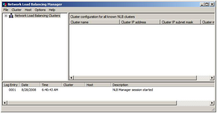
Network Load Balanced clusters are built using the Network Load Balancing Manager which may be launched from the Start -> All Programs -> Administrative Tools menu or from a command prompt by executing nlbmgr. Once loaded, the manager will appear as shown in the following figure:
To pre-configure the account and password credentials to be used on each node in the cluster, select Options -> Credentials and enter an account and password. Note that the account must be a member of the administrators group. If default credentials are configured, the user will be prompted for account and password information each time a connection to a cluster node is established.
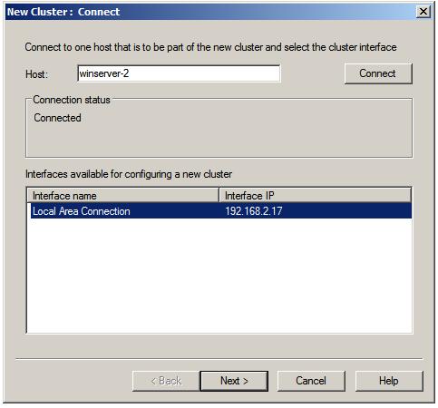
To begin the cluster creation process, right click on the Network Load Balancing Clusters entry in the left panel of the manager window and select the New Cluster menu option. This will display the New Cluster connection dialog. In this dialog, enter either the name or IP address of the first server to be included in the load balanced cluster and press the Connect button to establish a connection to that server. If the connection is successful the first server will be listed as shown below:
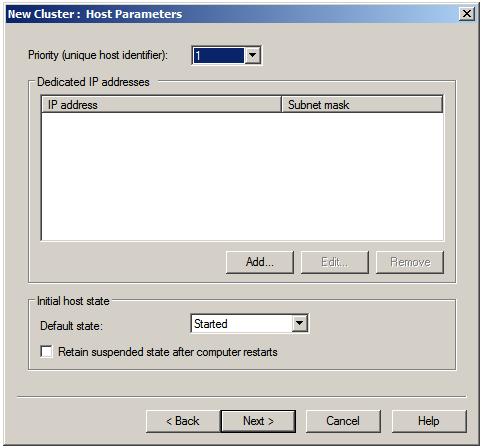
Clicking Next will display a warning that DHCP will be turned off for the network adapter of the specified host and that any necessary gateway information will need to be configured manually using the server's network connection properties dialog (accessible from the Control Panel). Subsequently, the Host Parameters screen will appear as shown below:
The Priority (unique host ID) is a number between 1 and 32 and serves two purposes. Firstly, the number provides a unique ID within the cluster to distinguish the server from other nodes. Secondly, it specifies the priority order of the cluster. The cluster node with the lowest priority is assigned to handle all traffic that is not covered by a port rule. All servers joining a cluster must have a unique ID. A new server attempting to join a cluster with a conflicting ID will be denied membership.
The Dedicated IP addresses fields are used when a single network adapter is used for both communication between cluster nodes and external network traffic. It is used to specify the host's unique IP address, which is used for non-cluster network traffic (i.e. direct connections to the specific server from outside the cluster without being affected by the Network Load Balancing). This must be a fixed IP address and not a DHCP address and as such should also be entered into the network properties dialog of the node. To configure dedicated IP addresses, click on the Add... button and enter the IP address and subnet mask (for example 255.255.255.0).
The Initial host state setting controls the initial state of the node when the system is started. The default is for the server to start as an active participant in the cluster. Alternative options are Suspend and Stop.
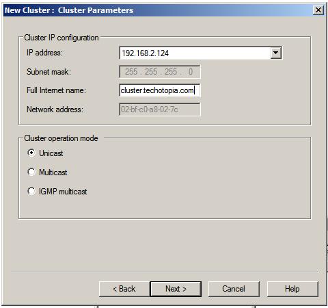
Clicking Next displays the Cluster IP addresses screen. These are the virtual IP addresses by which the cluster will be accessible on the network. These IP addresses are shared by all nodes in the cluster and a cluster may have multiple virtual IP addresses. Once the cluster IP addresses are specified, click on Next to proceed to the Cluster Parameters screen:
On this screen, enter the full internet name of the cluster (for example cluster.techotopia.com) and choose the appropriate Cluster operation mode. As outlined earlier in this chapter, the options here are Unicast, Multicast and IGMP multicast. IGMP multicast IPv4 addresses are limited to the Class D address range. Once selection is complete, click Next to proceed to the Port Rules screen:
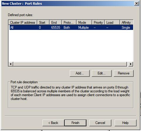
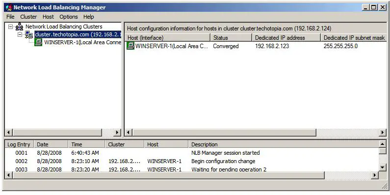
By default all TCP and UDP traffic on all ports (0 through 65535) is balanced across all nodes in the cluster with single client affinity. To define new or modify existing rules, for example to direct traffic to a particular port to a specific cluster node, use the Add and Edit buttons. Once port rules have been defined, click Finish to complete this phase of the configuration process. The Network Load Balancing Manager will now list the new cluster containing the single node as illustrated below:
With the cluster now configured and running, the next step is to add additional nodes to the cluster.
Adding and Removing Network Load Balanced Cluster Nodes
Before adding a new host to a cluster it is first necessary to install the Network Load Balancing feature on the new server as outlined previously in this chapter.
To add additional nodes to a Network Balanced Cluster, right click on the cluster in the left hand panel of the Network Load Balancing Manager and select Add Host To Cluster. If no cluster is currently listed, right click on Network Load Balancing Manager entry and select Connect to Existing. In the connection dialog enter the name or IP address of a node in the cluster (or the IP address of the cluster itself) and click on Connect. Once the connection is established, click on Finish to return to the manager interface where the cluster will be listed in the left hand panel using the cluster's full internet name.
To add a node, right click on the cluster name and select Add Host to Cluster. In the resulting dialog enter the name or IP address of the host to be added as a new cluster node and click on Connect. Once the connection is established, proceed to the next screen and specify the unique ID/ priority for the new node, together with dedicated IP addresses and the initial host state. Click Next to change any of the cluster port rule settings. Once finished, the new host will be listed in the manager screen with a status of Pending, followed by Converging and finally Converged.
Existing nodes in a cluster may be either suspended or removed. In either case, right click on the node in the Network Load Balancing Manager and select either Suspend or Delete Host. A suspended node may be resumed by selecting Resume from the same menu. A deleted node must be added to the cluster once again using the steps outlined above.
| Purchase and download the full PDF and ePub versions of this eBook only $9.99 |


